3D diamond cut laser measurement

3D diamond cut laser measurement
DCMT|3D – 3D DIAMOND CUT LASER MEASUREMENT
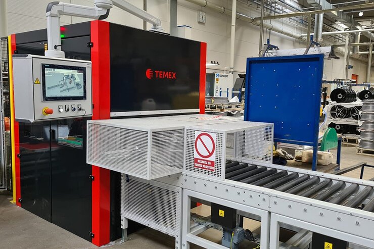
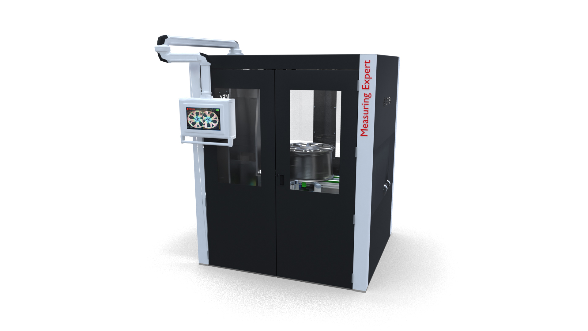
The DCMT|3D (Diamond Cut Measurement Tool) is a state-of-the-art device for 3D laser measurement of the visual side of aluminium wheels prior to the diamond cut process. The unique three-dimensional mapping of the visual side of wheel results in absolutely accurate dimensional data for CNC machine correction prior to machining.
BASIC CHARACTERISTICS
The first of the many advantages of this complex equipment is the ability to be quickly deployed into an existing production process. The measuring unit is supplied as a stand-alone device, which is suitable for easy integration into an existing production flow.
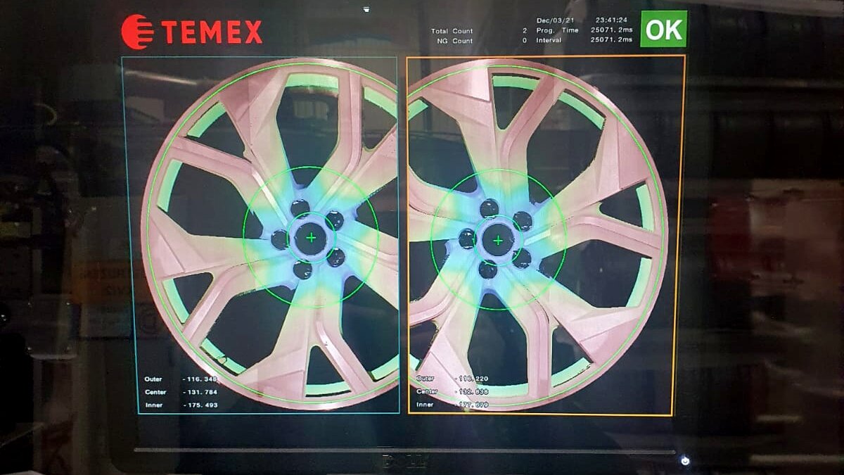
The result of the entire measurement process is accurate information about the deformations and irregularities of the casting. Based on this, correction data is calculated and transmitted to the CNC lathe. This data allows additional adjustment of the parameters required for machining.
The main benefit of the DCMT|3D is therefore a significant reduction of scrap in terms of the number of OK wheels after the first machining. This eliminates the need to rework the wheels and thus the increase in production costs. The DCMT|3D significantly increases lathe productivity and production capacity.
FUNCTION
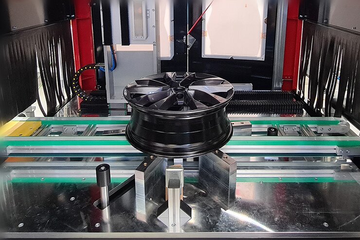
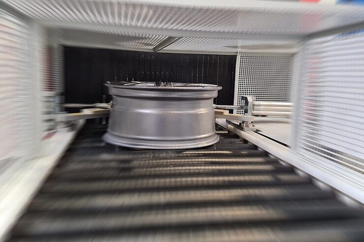
The 3D measuring wheels enter the device on an integrated conveyor, inside they are clamped and centered in all directions by means of jaws. Subsequently, the entire surface of the wheel face is scanned from above using a laser measuring device.
Based on the measured data, the machine generates an authentic 3D model of the wheel´s visual side, maps the distortions and irregularities of the casting, determines the deepest points in comparison with the reference wheel pattern and calculates the necessary correction values for the CNC lathe. These data are then transferred to the CNC machine. Based on these, the lathe will correct the position of the wheel prior to the machining process.
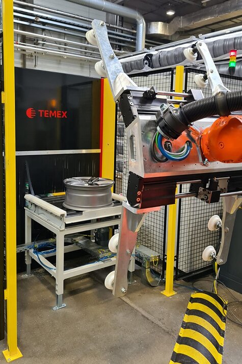
At the end of the process, the measured wheel is ejected using an integrated conveyor from which it can be either manually or robotically removed and placed in the lathe for the actual machining process.
TECHNICAL DATA
| Wheel parameters | wheel size wheel height wheel weight |
14″ – 24″ 4″ – 13,5″ 6 kg – 35 kg |
| Performance | machine capacity | 120 wheels/hour with 19″ |
| Controls | HMI control system |
touch display / process visualization SIEMENS |
| Measurement method | type | 3D laser |
| Machine dimensions | length width height |
1 845 mm 1 580 mm 2 272 mm |
| Machine weight | weight | 1 300 Kg |
Benefity
- Standardized and state-of-the-art solution for accurate visual wheel side measurement
- Precise measurement and transfer of correction data to the lathe has a significant impact on the reduction of nOK of manufactured wheels after the first machining
- The result is an increase in efficiency, productivity and thus production capacity
- The machine is delivered fully assembled = very fast deployment into existing production processes
- Operating mode up to 24/7/365