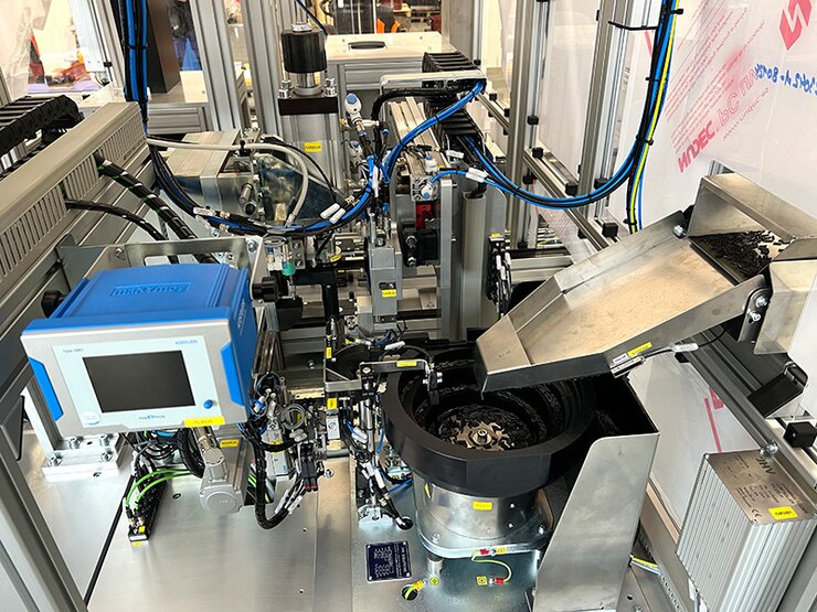
Phaser Assembly Production Line

The line is used to assemble and test a technologically advanced component (CAMPHASER) that allows a specific engine type to achieve better performance and efficiency through advanced valve timing control.

PHASER ASSEMBLY LINE
Realization date: 2023-2024
It is a semi-automatic line with two operators, designed for loading the input assembly components. It is divided into 6 basic sections + pallet conveyor lines, where each section contains several production stations. The line is designed to perform assembly and post-testing of the following products: GME-T6 Exhaust and GME-T6 Intake.
Brief description of individual modules and stations
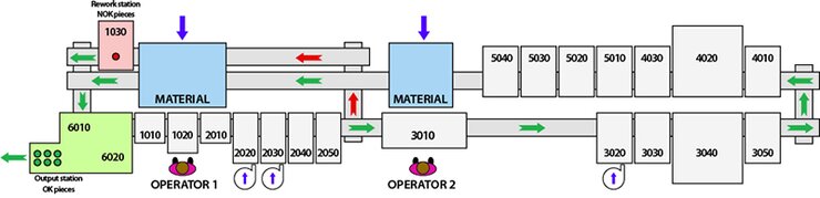
Module 1000 (contains 3 stations)
- Station 1010 – used to clean the upper part of the pallet from possible impurities generated in the process.
- Station 1020 – used for loading the input assembly material by operator 1. The loaded material is then visually checked by the operator and also by means of a camera sensor.
- Station 1030 – the station is located on the branch, which is designed for rework and deposition of NOK pieces.
Module 2000 (contains 4 stations)
Used for pre-assembly of the ROTOR assembly.
- Station 2010 – used to check the cross holes cut on the ROTOR using the camera system.
- Station 2020 – used to assemble the CAM PIN into the ROTOR body using a vibratory feeder and a 2D manipulator and gripper.
- Station 2030 – used to mount two COILED PINs into the SPACER body using a vibratory feeder and a 2D manipulator and gripper.
- Station 2040 – used to mount the ROTOR to the SPACE body using a 2D manipulator and gripper.
- Station 2050 – used to clean the ROTOR assembly with the SPACER from possible debris generated during the assembly process.
Behind this module, there is a junction on the conveyor line that allows the OK branch to be connected to the NOK branch if any of the results of the ROTOR assembly pre-assembly are evaluated by the system as NOK (Module 2000).
Module 3000 (contains 5 stations)
- Station 3010 – used for loading the input assembly material by operator 2.
- Station 3020 – used to establish the remaining three SCREWs through the DISC and STATOR body.
- Station 3030 – used to blow the pre-assembly of the PHASER, prior to the final bolting of the components together.
- Station 3040 – used to set the Lock Pin and screw the components together.
- Station 3050 – used to install the Return SPRING on the DISC body.
Module 4000 (contains 3 stations)
- Station 4010 – used to blow out and clean the PHASER pre-assembly before performing a functional test.
- Station 4020 – used to set up to perform functional tests on the product:
1. Leak test of the PHASER when the Lock PIN is placed in both end positions.
2. Measurement of the angle of movement of the ROTOR & SPROCKER
3. Measurement of the friction torque during the movement of the ROTOR
4. Measurement of Lock PIN clearance
5. Measurement of Lock PIN functionality - Station 4030 – used to install the COVER on the PHASER body.
Module 5000 (contains 3 stations)
- Station 5010 – used to roughen the underside of the ROTOR using a laser instrument.
- Station 5030 – used to imprint the COVER with identification marks and DMC code using a laser machine.
- Station 5040 – used to verify the laser marking placed on the COVER.
Module 6000 (contains 2 stations)
- Station 6010 – used to preserve the final product with oil mist.
- Station 6020 – used to place the final product on the output conveyor.