Retrofitting a pyrolysis-torrefaction unit

LABORATORY RETROFITTING MODULE – RETROFITTING A PYROLYSIS-TORREFACTION UNIT
Name of contract: Research laboratory retrofitting module
Term of delivery: 2019
SPECIFICATION
The project was implemented based on a customer inquiry and the fact that a Temex employee had experience with this technology.
The main requirement of the customer was focused on renovating the original equipment and to provide new components according to the specification for improving the process.
BASIC CHARACTERISTICS
Description of the existing pyrolysis-torrefaction equipment
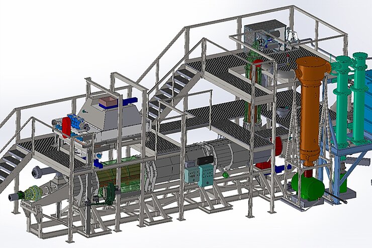
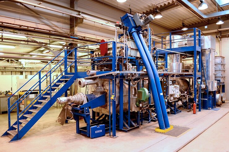
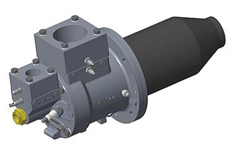
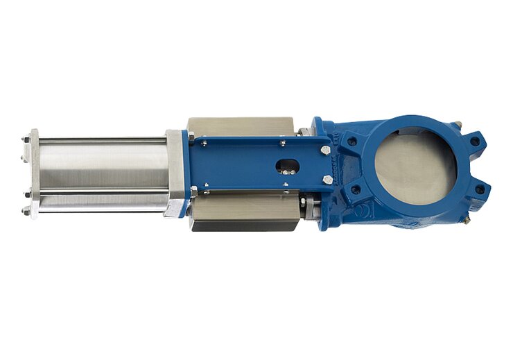
The unit (Figure 1a, b) is a device that serves to thermally destabilize materials without access to oxidizing media. The operation involves heating the material above the thermal stability limit of the organic compounds present, while the bonds of high molecular weight substances are broken down into low molecular weight products and solid residue. This process takes place in the retort of the pyrolysis-torrefaction unit. The retort consists of a heat-resistant tube and screw with a core. The material of the retort is AISI309 heat-resistant stainless steel with resistance up to 1000°C.
The heat for the process inside the retort is provided by two gas burners using natural gas, the hot flue gases of which flow in the flue gas line between the retort and outer casing. It is heated by a gas burner. The temperature in the retort is controlled by five thermocouples. The main part of the retort is the retort screw, which is used to move the incoming material through the retort and to degas it. The retort screw is driven by two 2.2 kW drives.
The pyrolysis or torrefaction gas produced is discharged from the retort via a gas pipe to the cooler section, where it is cooled and the condensable components are liquefied. The output of the solid residue from the process is designed as overflow from the retort to the first discharge screw of the coke plant. The coke plant is designed for cooling the pyrolysis or torrefaction residue and its safe transport outside the facility.
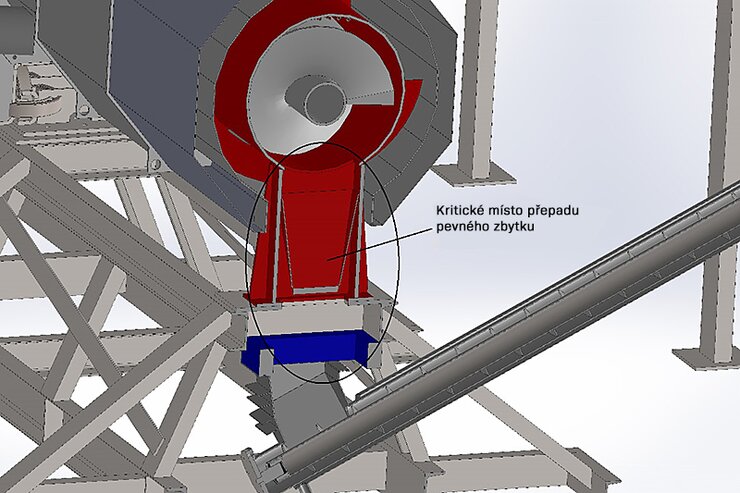
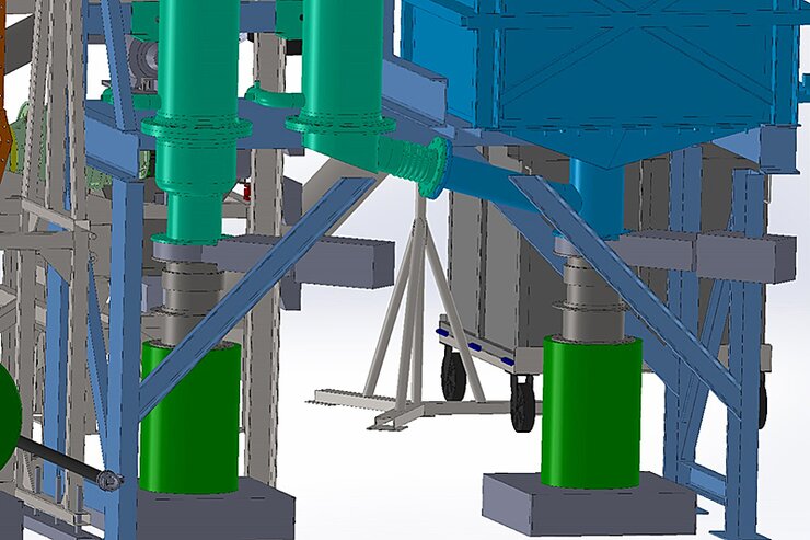
1. Modifying the output of the solid residue
During the operation of the Pyromatic 250 pilot plant thermal unit, it was found that the solid residue overflow, which is designed as a tapering funnel to accommodate the connection to the subsequent discharge screw conveyor, is unsatisfactory on account of the frequent arching of the solid residue, which leads to the complete clogging up and forced termination of the operation.
2. Heating up the pyrolysis-torrefaction unit
During the operation of the Pyromatic 250 thermal unit, it was likewise found that the heat distribution is uneven, especially in the central part of the unit. This precluded achieving optimal operation and a constant temperature, which affects the output products of the process.
3. Water coolers and the addition of measuring elements
Water coolers are used to cool the pyrolysis and torrefaction gases produced and the subsequent condensation of liquid hydrocarbons and water vapor, which liquefy at a given temperature and pressure in the individual stages of the water coolers.
4. Modifying the water cooler
During the course of modifying and changing the technology, the third water cooler was inspected for possible damage. It was found that coolant has been entering the gas line. This can be caused by cracked welds in the cooling pipes. If this defect cannot be rectified, the third cooler will be replaced with a new tubular cooler. The type and size of the new cooler will be at least comparable to the existing heatsink.
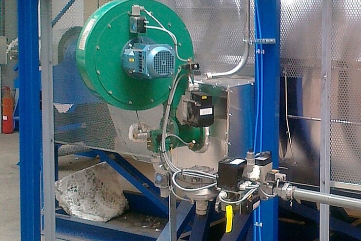
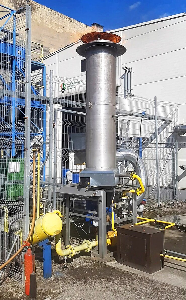
5. Pyrolysis or torrefaction gas combustion chamber
For the needs of the liquidation of the pyrolysis or torrefaction gas, a combustion chamber will be included in the technology of the thermal utilization of organic materials. Cooled gas that can be contaminated with hydrocarbon compounds – tar – is presumed in the design of the combustion chamber for burning the gas produced.
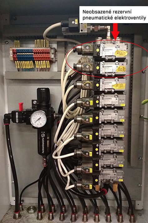
6. Úprava a doplnění elektro části
The individual parts of this document describe and recommend various types of pressure and temperature sensors and other additional equipment that need the supply of power and the input and output of control signals for their functionality. As such, data and power cables, cable guards, modifications and additions to cable trays, safety and switching elements and other electrical elements necessary for the safe and trouble-free operation of these supplemented devices are an integral part of completing the electrical part. This also includes modifying visualization with the addition of the new devices – visualization control web 7.
Key benefits of our solution:
- Research and development of special equipment together with the Technical University of Ostrava