MAN equipment lifespan

DELIVERY OF A MACHINE TO TEST THE LIFESPAN OF THE MAN STEERING WHEEL LOCK ASSEMBLY
Name of contract: Lifespan tester for MAN equipment
Term of delivery: 2017-2018
SPECIFICATION
The project was implemented at the request of the customer for the design and manufacture of lifespan equipment. The equipment is part of their testing laboratory.
SOLUTION – PARAMETERS
Operational cycle: Set up using a touch screen
Capacity of the equipment: The number of test cycles can be set up using the touch screen
DESCRIPTION OF THE AUTOMATED PROCESS
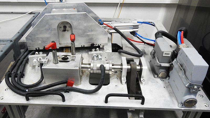
1. The operator places the MAN steering wheel lock assembly into the loading jig. The loading jig is shaped so that the lock assembly cannot be inserted the wrong way.
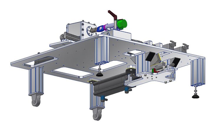
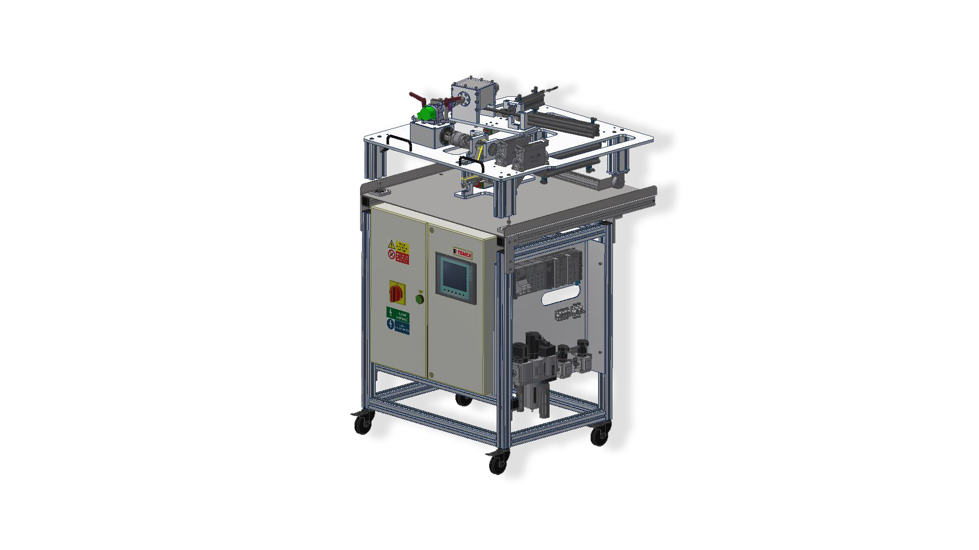
2. Once inserted, the operator attaches 2 spacer cylinders to the studs and secures the lock assembly with manual locking levers. This prepares the jig for entry into a temperature test chamber of -40°C to +90°C, including 95% humidity. The jig is equipped with wheels in the front part to facilitate entry into the chamber; the back has adjustable legs.
3. After entering the temperature chamber, the operator ensures the leeway of the connecting cables between the jig and trolley, which is outside the temperature chamber, and connects them using HARTING connectors. The trolley is equipped with an operator panel for controlling the jig in the temperature chamber. The cycle is constantly repeated according to the selected program.
BASIC CHARACTERISTICS
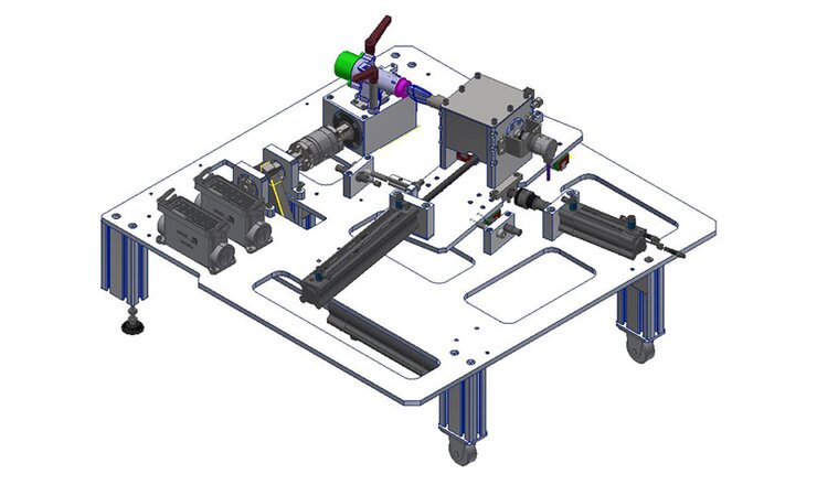
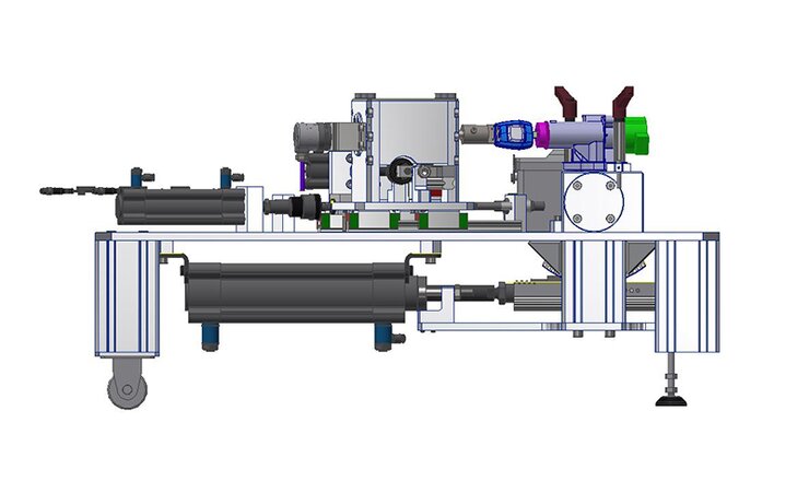
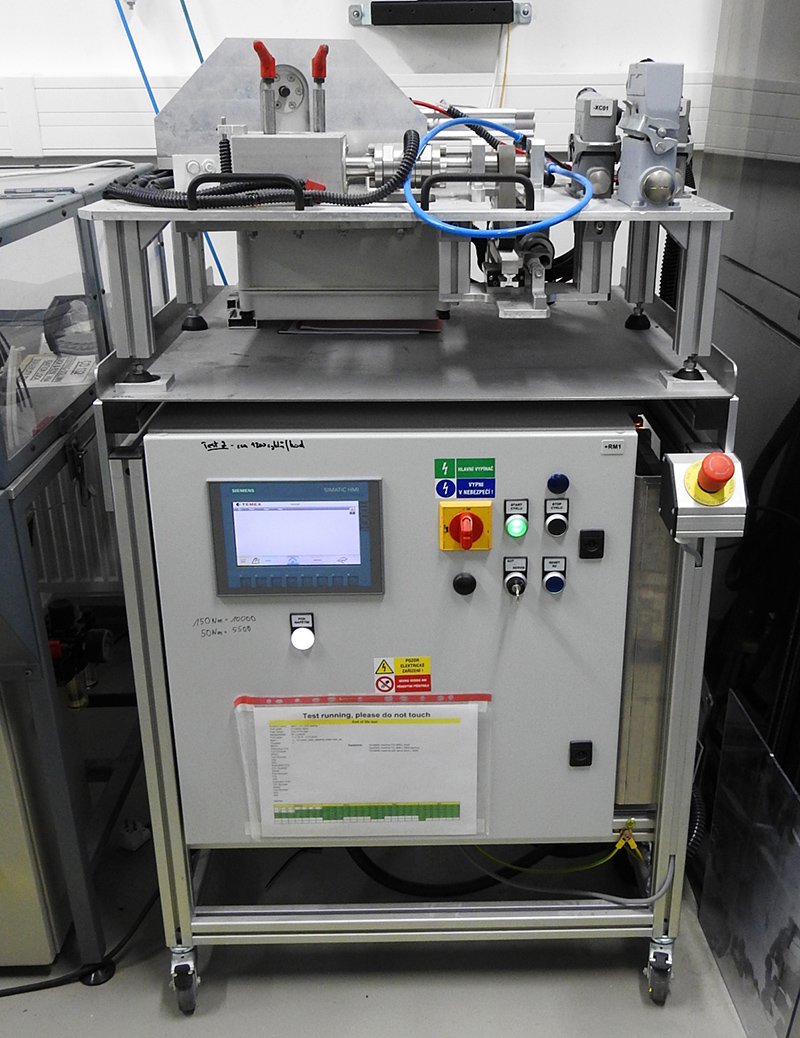
The machine is designed as a test station. It consists of a main aluminum frame and stainless steel mobile table, a mobile test plate for the MAN steering lock rods and the necessary cabling. The inserted lock assembly is placed on a POKA YOKE bed and manually secured by the operator. The status of the machine is displayed by the operation panel and indicators. From the point of view of safety, this machine is designed to work within the enclosed space of the temperature test chamber, and so it is not equipped with a special cover, door, etc.
Key benefits of our solution
- Saves time
- Eliminates work-related injuries during handling
- Test statistics