Assembly line for EGR valve cooler cover


Robotic assembly line offering maximum performance thanks to the complete automation of the production process
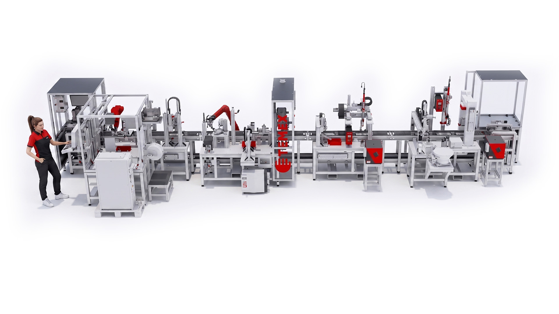
Assembly line for EGR valve cooler cover
Project: Assembly line sensor for VW cover
Number of workstations within the equipment: 11+1
Term of delivery: 2019-2020
PARAMETERS:
Length: 9500 mm
Depth: 2800 mm
Height: 2000 mm
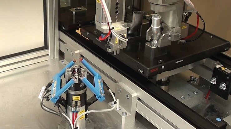
Robots: Fanuc LR Mate 200 iD 7L
Line cycle: 50 sec/pc
EQUIPMENT OPERATION:
The assembly line assembles the sensor cover for the EGR valve cooler. It completes the finished assembly of 7 components, some of which are transferred on a conveyor belt pallet during the production process. Others are delivered from bins at the individual workstations. The conveyor belt runs at two levels – the upper level is used to transfer components between individual workstations; the lower level is used to transfer the finished assembly back to the operator. At both ends of the line, elevators move the pallets between the levels. Two FANUC robotic arms aid the high output and fast line cycle.
DESCRIPTION OF THE EQUIPMENT AND INDIVIDUAL STATIONS:
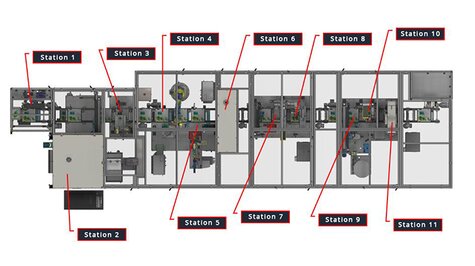
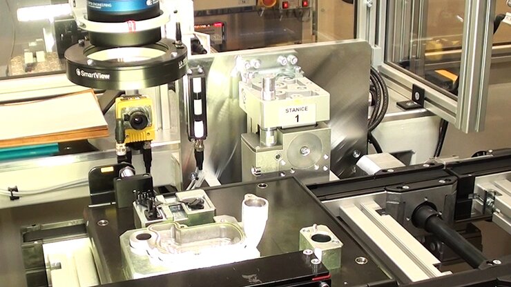
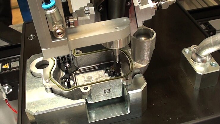
Station 1
• Removing the manufactured assembly
• Certain components installed by the operator – cover with mounted seal and lead frame
• Automatic checking for the presence of components, for the correct quality of the lead frame and proper installation of the seal in the aluminium body of the cover
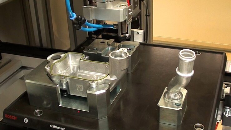
Station 2
• Pressing the water tube into the flange
• Welding using the TIG method
• The tube and flange are transferred to the station by the operator
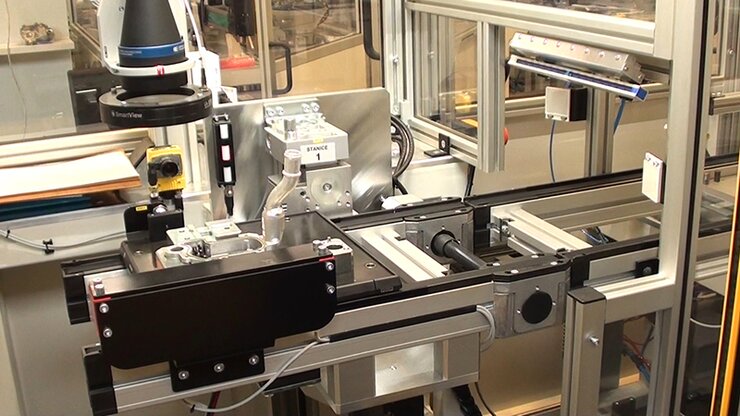
Station 3
• Electrical test of lead frame contacts
• Laser marking of the cover with a DMC code
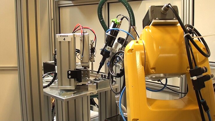
Station 4
• Plasma cleaning of the lead frame
• Bending of the lead frame pins
• Application of the first layer of adhesive at the location of the sensor and camera inspection
Station 5
• Removing the sensor (Melexis chip) from the disc and placing it on the applied adhesive in the lead frame
• Irradiation and curing with a UV lamp
• Camera inspection of the attached sensor
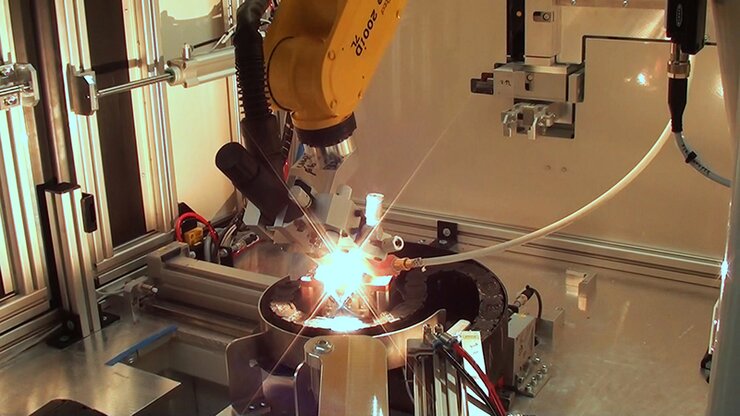
Station 6
• Laser welding of the sensor contacts to the bent lead frame contacts
Station 7
• Electrically testing the lead frame with sensor
• Inserting the lead frame into the aluminium cover
Station 8
• Screwing the lead frame to the cover
Station 9
• Attaching the O-ring to the flange of the flanged water tube subassembly
• Cooling the subassembly and mounting the flanged tube to the cover
Station 10
• Screwing the flanged tube subassembly to the cover
Station 11
• The cover and flanged tube assembly leak test
Station 12
• Pallet elevator to move the pallet with the finished assembly down to the lower branch of the conveyor
LAYOUT OF COMPONENTS ON THE PALLET:
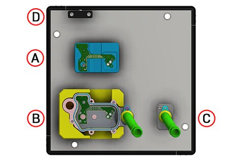
A) Jig for the lead frame
B) Jig for the cover
C) Jig for the welded flanged water tube
D) RFID chip holder
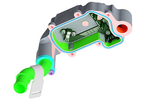
FINAL ASSEMBLY:
DESIGN OF THE EQUIPMENT:
The assembly line´s design is a combination of a semi-automated and fully automated line for one-person operation. It consists of 11 workstations with pallets and a pallet conveyor for transferring the assembly components between each station. The last station is an elevator between the upper and lower conveyor belt.
Each workstation´s structural basis is a welded steel frame and prefabricated frame made out of aluminium profiles.
Stations 1 and 2 are the operator’s station. They are both equipped with control box, static and mobile operator panel, component insertion signal light and a camera system monitor.
All workstations contain many inspection detectors, ensuring the presence of individual parts and their correct positions.
Safety is ensured by a sheet metal and lexan cover, light barriers and automatic security doors with electric locks.