
Robotic EGR valve cooler assembly line – 2nd generation
Robotic assembly line with maximum performance thanks to complete automation of the production process
Robotic EGR valve cooler assembly line – 2nd generation
Project: Robotic EGR cooler assembly line GEN2
Number of positions within the line: 6
Term of delivery: 2015 – 2016
PARAMETERS:
Length: 5800 mm
Depth: 5600 mm
Height: 2500 mm
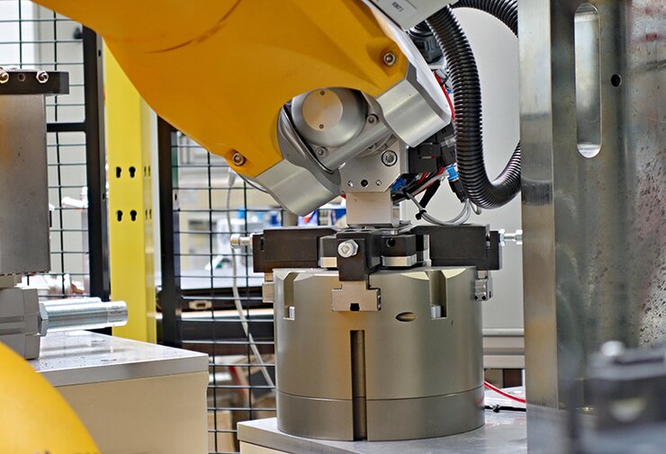
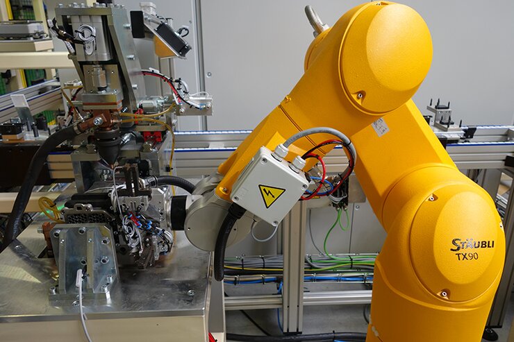
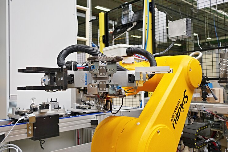
Robots: Staübli TX90; Fisnar F5200N
Line cycle: 60 sec/pc
FEATURES:
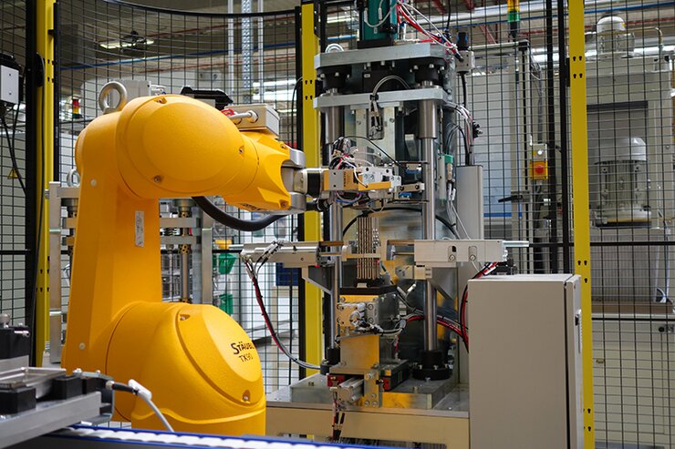
The robotic line assembles coolers for the EGR valve. The finished product consists of 7 + 71 components. Seven essential elements are moved on pallets, 71 tubes are automatically loaded from exchangeable containers. The conveyor system operates 16 pallets and has six stations + 6 waiting positions (buffers). The large number of workstations served by separate robotic arms and a higher number of pallets moving individual parts means the automatic line achieves an excellent working cycle (sec/pc).
DESCRIPTION OF THE WORKSTATIONS:
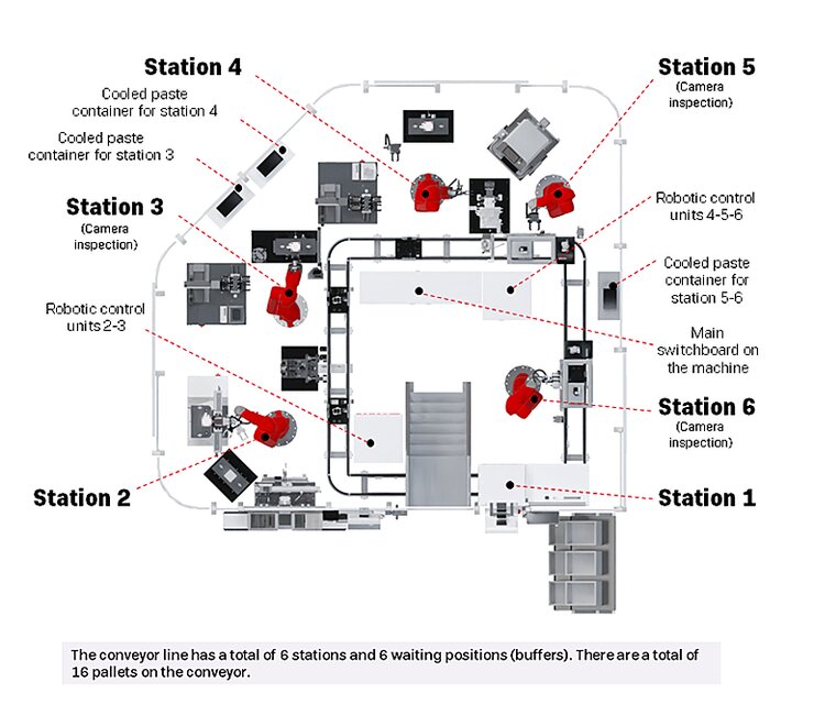
Station 1
• Loading of input components / removal of finished workpieces (OK and NOK) and their placement/packaging in boxes by the operator
Station 2
• Scooping up 71 tubes for the jigs
• Outer casing calibration
• Installation of the water adapter on the outer casing (cooperation with the robotic arm at Station 3)
• Sliding the outer casing onto the tubes, threading the upper and lower caps and tamping the ends of the tubes
Station 3
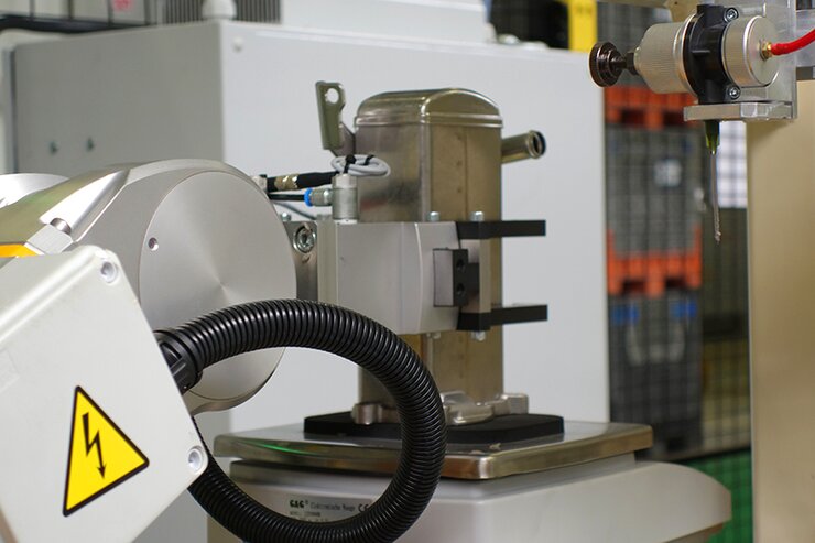
• Weighing the workpiece and pasting half of the tubes with solder paste
• Calibration of the outer cap
• Installation of the outer cap – pressing
Station 4
• Weighing the workpiece and pasting the other half of the tubes with solder paste
• Flange installation – pressing
• Spot welding the bracket onto the outer casing of the cooler
Station 5
• Cooling the workpiece
• Weighing the workpiece
• Pasting half of the casing
• Camera inspection of the correctness of pasting
Station 6
• Weighing the workpiece
• Pasting the other half of the casing
• Camera inspection of the correctness of pasting
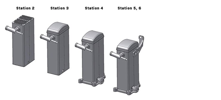
OUTPUT STATUS OF THE COOLER FROM INDIVIDUAL STATIONS:
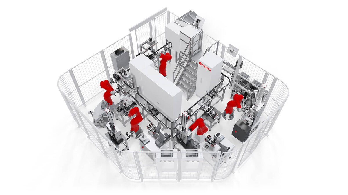
DESIGN OF THE LINE EQUIPMENT:
The production line is designed as a set of automated workstations for one-person operation. It consists of assembled welded frames, aluminium structures, conveyors and robots.
The entire production line has six workstations. Station 1 is the operator’s workplace, the other workstations are fully automated with robotic arms, and the operator has no access to these workstations (except for service and maintenance). Station 1 also has a control box with Start, Reset and Total Stop buttons, an operator panel, lights indicating component placement, and camera system monitors.
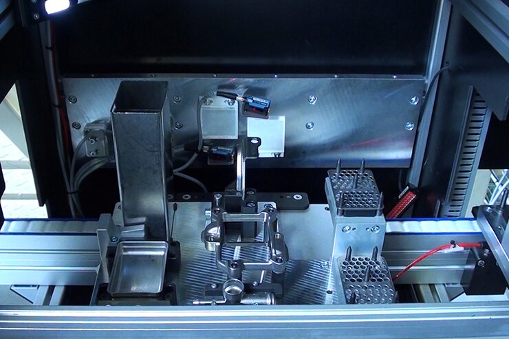
All workstations contain many inspection sensors – both laser and camera, ensuring the presence of the individual parts and their correct positions.
The primary and main safety feature is fencing with safety doors. Other safety features include safety covers with smoky Plexiglas to prevent light getting out and sliding doors with a Tapeswitch safety bar.
")
")


