Camera inspection and packaging of ferrite cores


CAMERA INSPECTION AND PACKAGING OF FERRITE CORES
Name of contract: Modular machine for optical inspection and packing of circular ferrite cores
Term of delivery: in progress
SPECIFICATION
The end of ferrite cores production sees two manually performed operations: the optical inspection of the cores and their insertion into the packaging unit (polystyrene pallet).
The project aims to make an automated device that combines the optical inspection of circular ferrite cores and the subsequent loading of them into polystyrene blisters (pallets).
SOLUTION – PARAMETERS
Machine cycle: 2 seconds per core
Input tray capacity: 10 plates (or more)
BASIC CHARACTERISTICS
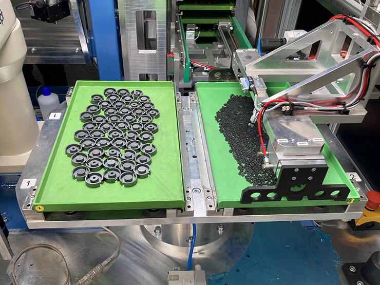
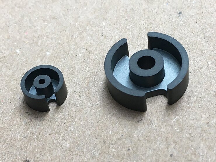
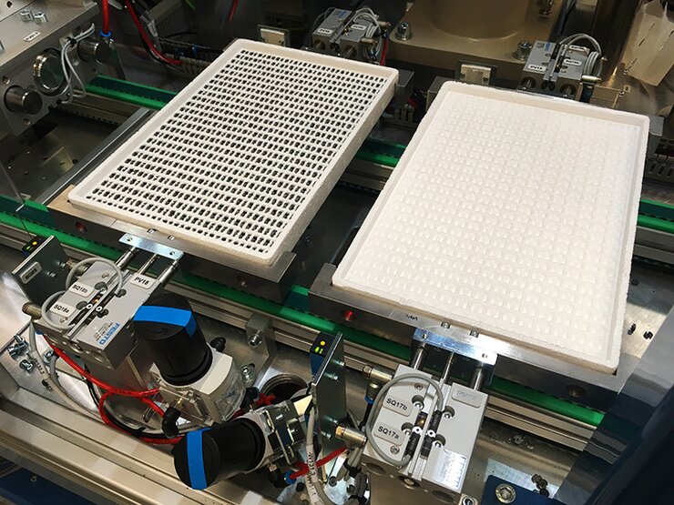
The device is designed for the fully automated visual inspection of circular ferrite cores. The ferrite cores are placed on plastic plates at the entrance to the machine, with fixed dimensions. Ferrite cores are circular in size variations:
Range of the diameters of tested cores: 7–36 mm
Range of the heights of tested cores: 3–25 mm
The output from the machine is an entirely full polystyrene pallet with OK ferrite cores. The floor plan dimensions of the output pallet are the same for all variations of core dimensions. The height of the pallet varies. The pallets are stacked in columns at the machine´s exit (one column of empty pallets, the other column of pallets full of ferrite cores).
The handling of input plates at the entrance to the machine and the handling of pallets at the exit of the machine is done manually by the machine operator.
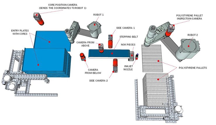
DESCRIPTION OF THE AUTOMATED PROCESS
1. The plate slides out of the tray. The camera above the plate focuses on the individual cores´ positions and sends the coordinates to robot 1. Unrecognized pieces may remain lying on the plate.
2. Robot 1 collects individual pieces from the plate – when moving to the sorting belt, it stops for the time needed to take a snap above the camera “from below”. It puts the core on the belt.
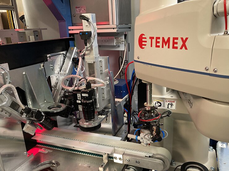
3. The belt performs the next step – the core enters below the camera “from above” and stops for the time necessary to take a control snap.
4. The same as in step 3 for the two side cameras.
5. The next step of the belt after the side cameras is to evaluate whether the core is OK or NOK. The OK core is gripped by robot 2. The NOK core is allowed to fall from the belt into the scrap bin in the next step.
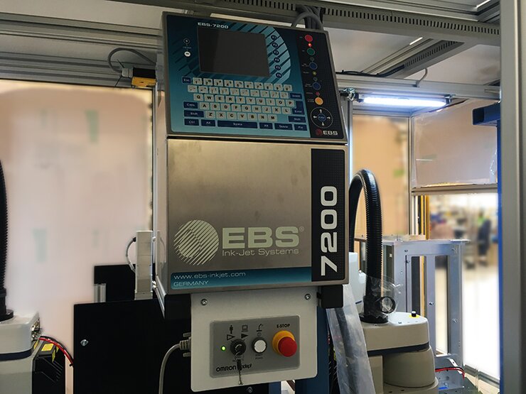
6. Robot 2 grips the OK core, most often from the side (due to most of the placement on the pallet being on the edge), or from above, and when moving to the pallet it passes over the inkjet nozzle – printing, marking of the cores. It then places it on the pallet.
7. When finished, the camera above the pallet checks to see if the fullness matches the expected pattern
Key benefits of our solution
- Significant savings in human resources for shift work
- 100% elimination of manually handling considerable weight loads in the entire packaging process
- Increasing production capacity
- Full automation of the whole packaging and palletizing process